Material Removal Simulation
The Material Removal Simulation is a dynamic step-by-step visualization of the material removal process. It provides a detailed simulation of how a tool cuts a part or stock, allowing you to observe each stage of the machining process.
You should follow these steps to properly simulate material removal with RoboDK CAM:
1.The cutter must be defined.
2.Link the robot or CNC if there are more than one robot arm in the station.
3.Specify the stock object.
4.Enable cutting simulation. Otherwise, the simulation will run without material removal.
Link the robot
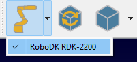
Use the down arrow on the Link Robot button to bring up a menu of available robots and link the simulation to one of them. If the button is in selected state (the robot is linked), pressing it will cause the robot to disconnect from the simulation.
The linking between the robot and the simulation can also be done using the context menu in the station tree.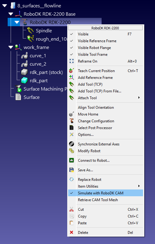
Once the robot is linked to the simulation, any robot movements in the RoboDK window will be repeated by the simulator as tool movements. Regardless of the source of this movement: a RoboDK program, a Python script, or manual movement with a mouse.
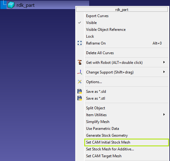
Definition of the stock object
Right-click on the stock object in the RoboDK station tree and select Set CAM Initial Stock Mesh.
Generation of the stock object
Right-click on the stock object in the RoboDK station tree and select Generate Stock Geometry.
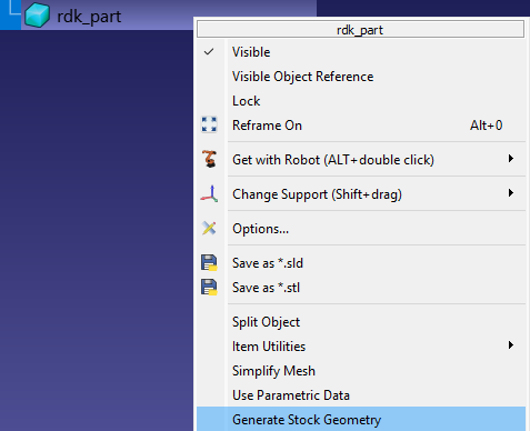
This command will launch the stock creation utility, which uses the original model shape for the generation process.
There are three methods for generating stocks:
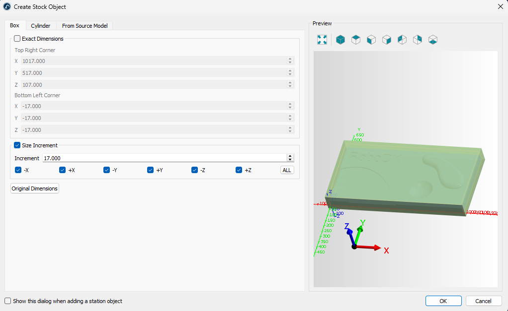
1.Bounding box – Box tab
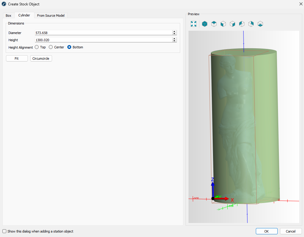
2.Bounding cylinder – Cylinder tab
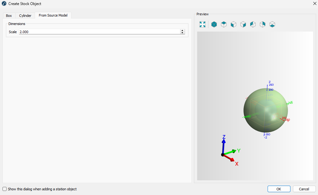
3.Scaling – From Source Model tab
On the Box tab, you can specify the exact dimensions of the bounding box or generate it by extracting (using the Original Dimensions button) and enlarging specific dimensions.
The Cylinder tab allows you to create a stock in the form of a cylinder containing the original model.
The From Source Model tab allows you to create a stock in the form of a scaled original model.
Stock View
Once the stock definition is complete, the simulation stock model will be displayed on top of the other models in the RoboDK scene. You can control the view of the stock simulation using the Stock View submenu on the toolbar:
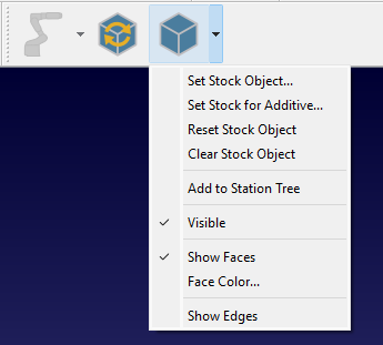
Set Stock Object – define/redefine a stock object.
Set Stock for Additive Object – define/redefine an additive stock object.
Reset Stock Object – revert the stock to its initial state.
Clear Stock Object – delete a stock object.
Add to Station Tree – copy the stock in its current state as as model into the RoboDK station tree.
Visible – stock visibility switch.
Show Faces – show stock faces.
Face Color… – set the default color for the faces.
Show Edges – show stock edges.
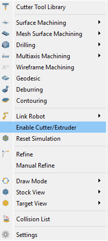
Activate material removal simulation
Material removal simulation is activated automatically. However, you can control it manually using the CAM-Enable Cutter/Extruder command.
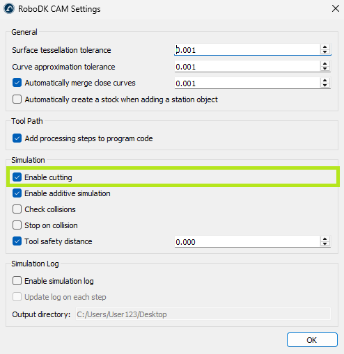
Also, it’s necessary to check if the CAM-Settings-Simulation-Enable cutting setting is active.
Reset Simulation
Simulation reset command reverts the stock to its initial state.

Target View
You can compare the current state of the stock with the target model. To do this, you first need to set the target model using CAM-Target View-Set Target Object, and then apply CAM-Draw Mode-Deviation Map.
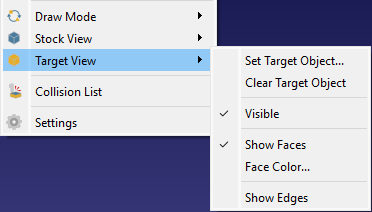
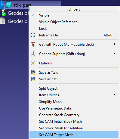
To set the target object, you can also right-click on the model in the station tree and select the Set CAM Target Mesh command.
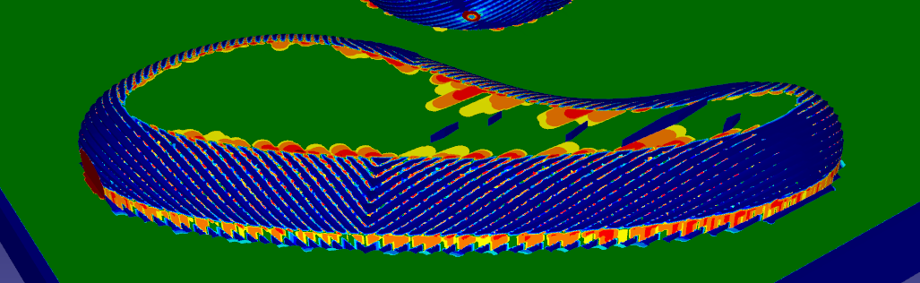
Deviation Map
The deviation map shows the relative difference using a colour scale ranging from green, indicating no difference, to red, indicating the greatest difference.
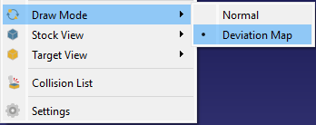
Select CAM-Draw Mode-Deviation Map to show the defiation map.
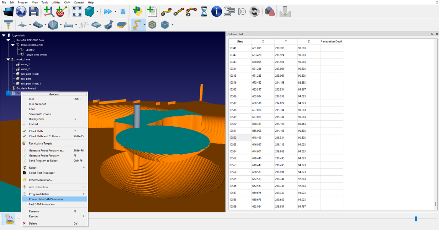
Collision List
The collision list shows the sequence of collisions between the non-cutting parts of the cutter tool (e.g. holder) and the workpiece during machining.
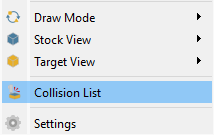
Select CAM-Collision List to show the collision list.
Refine/Manual Refine
With the Refine option enabled, you can obtain higher-quality surface visualization during simulation (this may affect rendering performance).
Using the Manual Refine command, you can improve the visualization of surfaces once after pressing it.
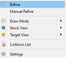
Select CAM-Refine / CAM-Manual Refine to perform the refine operation.
Fast CAM Simulation
You can run a quick simulation of material removal. To do this, right-click on the target program and select the Fast CAM Simulation command.